Injection molding design guidelines and tolerances
Designing plastic parts for injection molding requires adherence to core Design for Manufacturing principles: uniform wall thickness between 1.5 mm and 3.5 mm, draft angles of at least one degree on all vertical faces, generous corner radii, and structural ribs sized to fifty percent of nominal wall thickness. Designing to international tolerance standard DIN ISO 20457 ensures achievable fits without excessive tooling expense.

The foundational design rule: Uniform nominal wall thickness
The single most important rule in plastic component engineering is maintaining uniform wall thickness across the entire part geometry. Molten plastic is an inefficient thermal conductor. Thick cross sections take substantially longer to cool than adjacent thin walls, creating unequal volumetric shrinkage rates.
When thick sections shrink while adjacent thinner sections have already solidified, the internal contraction pulls surface skins inward, creating unsightly sink marks, internal structural voids, and severe component warpage.
Where wall thickness transitions are unavoidable, engineers should incorporate gradual tapered transitions with a slope of at least 3:1 rather than abrupt steps, allowing smooth laminar melt flow and balanced cooling.
Nominal wall thickness recommendations and linear shrinkage by resin
| Resin family | Recommended wall thickness range | Typical linear mold shrinkage | Recommended minimum draft per side |
|---|---|---|---|
| ABS (Acrylonitrile Butadiene Styrene) | 1.5 mm to 3.5 mm | 0.4% to 0.7% | 1.0 degree (2.0 degrees for light texture) |
| Polycarbonate (PC) | 1.8 mm to 3.8 mm | 0.5% to 0.8% | 1.0 to 1.5 degrees (high viscosity melt) |
| Polyamide 6 / 66 (Nylon PA) | 1.2 mm to 3.0 mm | 1.0% to 2.5% (unfilled) | 1.0 degree (increases when glass-filled) |
| Polypropylene (PP) | 1.0 mm to 3.5 mm | 1.2% to 2.2% (semi-crystalline) | 1.0 to 1.5 degrees |
| Polyoxymethylene (POM / Acetal) | 1.5 mm to 3.2 mm | 1.8% to 2.5% (high crystallization) | 1.0 to 1.5 degrees |
| Thermoplastic Elastomer (TPE) | 1.5 mm to 3.5 mm | 1.5% to 2.5% | 1.5 to 3.0 degrees (prevents friction drag) |
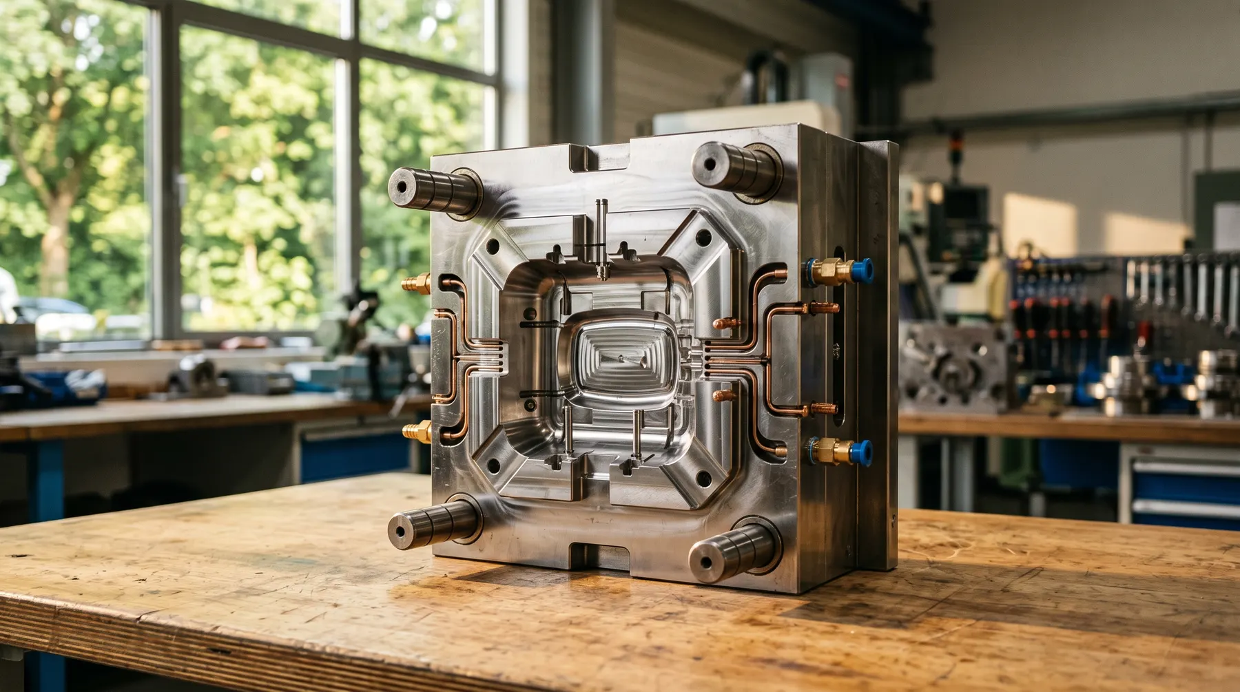
Draft angles: Enabling clean ejection without surface scuffing
Every surface parallel to the direction of mold opening requires draft: a slight taper angle that allows the molded part to break contact with the mold steel immediately upon platen separation.
Without adequate draft, cooling plastic contracts tightly around male mold cores, generating intense frictional drag during ejection. This drag results in unsightly scuff marks, excessive ejection pin witness marks, and in severe cases, parts sticking inside the mold cavity.
As a baseline rule of thumb, apply a minimum of 1.0 degree of draft per side for smooth polished surfaces. When specifying electrical discharge machining (EDM) spark finishes or chemical leather textures, add at least 1.0 to 1.5 degrees of additional draft for every 0.025 mm of texture depth.
Structural ribs, screw bosses, and corner radii
Increasing part stiffness should always be achieved by adding thin structural ribs rather than thickening nominal walls. To prevent sink marks on the opposite cosmetic surface, rib base thickness should measure between 50 and 60 percent of the adjoining nominal wall thickness.
Rib height should not exceed three times the nominal wall thickness to avoid filling hesitations and trapped air. Screw bosses designed to receive self-tapping screws should feature an outer diameter equal to 2.0 to 2.4 times the screw hole diameter, with supporting gusset ribs tying the boss into nearby structural walls.
Sharp corners create severe stress concentrations and restrict plastic melt flow. Internal corner radii should equal at least 50 to 60 percent of nominal wall thickness, with external radii sized at 150 percent of wall thickness to maintain consistent wall thickness around corners.
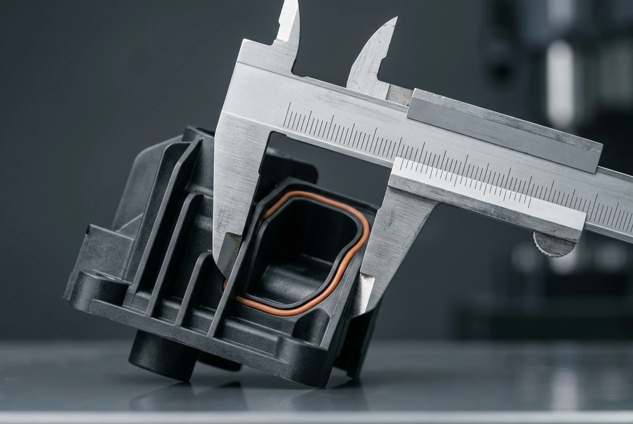

Understanding DIN ISO 20457 plastic molding tolerances
Plastic components cannot be held to metallic CNC milling tolerances due to anisotropic material shrinkage, thermal expansion, and ambient humidity absorption. The relevant European standard for molded plastics is DIN ISO 20457 (superseding the legacy DIN 16742 standard).
DIN ISO 20457 establishes tolerance groups (TG) based on part dimensions, resin shrinkage behavior, and mold tool precision. Tolerance Group TG6 represents standard commercial production achievable without exceptional cost.
Tolerance Group TG4 represents precision technical molding applicable to critical functional dimensions, requiring temperature-controlled tooling, high-precision steel inserts, and rigorous statistical process control. Tolerances apply at a standard reference temperature of 23 degrees Celsius and 50 percent relative humidity.
Recommended technical pages
Related manufacturing processes and guides
Explore engineering documentation, process limits, and material guidelines.

How injection molding works
Complete cycle analysis, clamp tonnage calculation, machine subsystems, and defects.

Materials guide
Compare ABS, PC, PA, PP, POM, and TPE resins by mechanical and regulatory profile.
Mold cost and lead times
Tooling cost variables, cavity numbers, steel grades, and delivery schedules.
Frequently asked questions
Direct technical answers on processes, tooling, standards and commercial terms.
What is a typical draft angle for injection molded thermoplastic components?
A standard guideline is at least 1.0 degree per side on all vertical surfaces. Textured or spark-eroded surfaces require additional draft, typically 1.0 to 1.5 degrees extra per 0.025 mm of texture depth.
Why must nominal wall thickness be kept uniform throughout a component?
Uniform wall thickness ensures consistent cooling rates across the part, preventing internal vacuum voids, differential shrinkage stresses, cosmetic sink marks, and dimensional warpage.
What is DIN ISO 20457 and how does it apply to European procurement?
DIN ISO 20457 is the European standard governing tolerances and acceptance conditions for plastic molded parts. It defines achievable tolerance groups such as standard TG6 and high precision TG4, and applies when agreed between buyer and molder.
What tolerances can realistically be achieved on molded plastic parts?
General dimensions typically achieve plus or minus 0.1 mm to 0.3 mm depending on overall length, resin shrinkage rate, and tool construction. Marking only functional fit dimensions as critical prevents unnecessary tooling inflation.
What is an undercut and how does it influence mold tooling cost?
An undercut is an internal or external feature that prevents straight line ejection along the primary mold opening axis. Undercuts require moving mechanical slides, lifters, or collapsible cores in the tooling, which increases mold fabrication complexity and cost.
Request a DFM review on your CAD models
Send STEP files for comprehensive draft, wall thickness, and parting line feedback. We highlight potential sink marks and suggest tooling improvements.