How injection molding works: process, steps and common defects
Injection molding is a cyclical manufacturing process where solid thermoplastic pellets are melted inside a heated barrel, homogenized by a rotating reciprocating screw, and injected under high pressure into a closed steel or aluminium mold cavity. Once the molten polymer cools and solidifies within the water-cooled mold channels, the tool opens and ejector pins push the finished part out.

The six sequential steps of the injection molding cycle
The injection molding process operates in a repeating six step cycle that converts raw thermoplastic granules into precision solid parts in seconds. The duration of this sequence, known as cycle time, typically ranges from fifteen seconds for thin-walled medical items to over sixty seconds for thick industrial housings.
Step 1 Clamping: The hydraulic or electric clamping unit closes the two halves of the mold together with immense force. Clamp force must counteract the separation force generated when pressurized molten plastic enters the cavity.
Step 2 Injection: The reciprocating screw moves forward linearly like a piston, forcing a precise volume of molten polymer, known as the shot, through the machine nozzle, sprue bushing, runner network, and narrow gates into the closed mold cavities.
Step 3 Pack and hold: Once the cavity fills, the screw maintains holding pressure against the molten plastic. This critical step compensates for volumetric thermal shrinkage as the resin transitions from melt to solid, preventing internal voids and surface sink marks.
Step 4 Cooling: While holding pressure ceases, the part continues to cool and solidify inside the temperature-regulated steel mold. Concurrently, the machine screw rotates backward, drawing fresh granules from the feed hopper, melting them through barrel heater bands and shear friction, and accumulating the next shot in front of the screw tip.
Step 5 Mold opening: Once the part reaches an ejection temperature below its heat deflection threshold, the movable platen retracts, separating the mold along its parting line.
Step 6 Ejection: Mechanical ejector pins, stripper plates, or pneumatic blasts advance from the movable core side, pushing the finished component free into a collection bin or onto a conveyor belt for inspection.
Common injection molding defects: Root causes and shop floor remedies
| Molding defect | Visual manifestation | Primary root causes | Engineering and process corrections |
|---|---|---|---|
| Flash | Thin excess plastic film along parting line or vents | Excessive injection pressure, worn tool parting surfaces, inadequate clamp tonnage | Increase machine clamp force, reduce pack pressure, repair mold shut-off lands |
| Sink marks | Depressions or dimples on surfaces opposite ribs or thick walls | Uneven wall thickness, insufficient hold pressure or short hold time, gate freezing early | Maintain uniform wall thickness, increase hold pressure and duration, enlarge gate diameter |
| Short shot | Incomplete filling of cavity leaving missing features | Insufficient shot size, cold melt temperature, high melt viscosity, inadequate mold venting | Increase melt temperature, enlarge venting grooves, raise injection speed or barrel shot volume |
| Weld lines | Visible hairline seam where two melt flow fronts meet | Low melt front temperature, slow injection speed, entrapped air at flow junction | Raise mold temperature, position gates to relocate knit line to non-critical areas, add local vents |
| Warpage | Dimensional distortion or twisting after part cooling | Non-uniform cooling rates between core and cavity, unbalanced volumetric shrinkage | Balance mold water cooling channels, ensure uniform wall thickness, adjust holding pressure |
| Burn marks | Black or dark brown charred spots near flow end | Trapped air compressed and ignited by diesel effect due to inadequate venting | Add mold perimeter vents, clean clogged vent channels, reduce injection velocity in final fill |
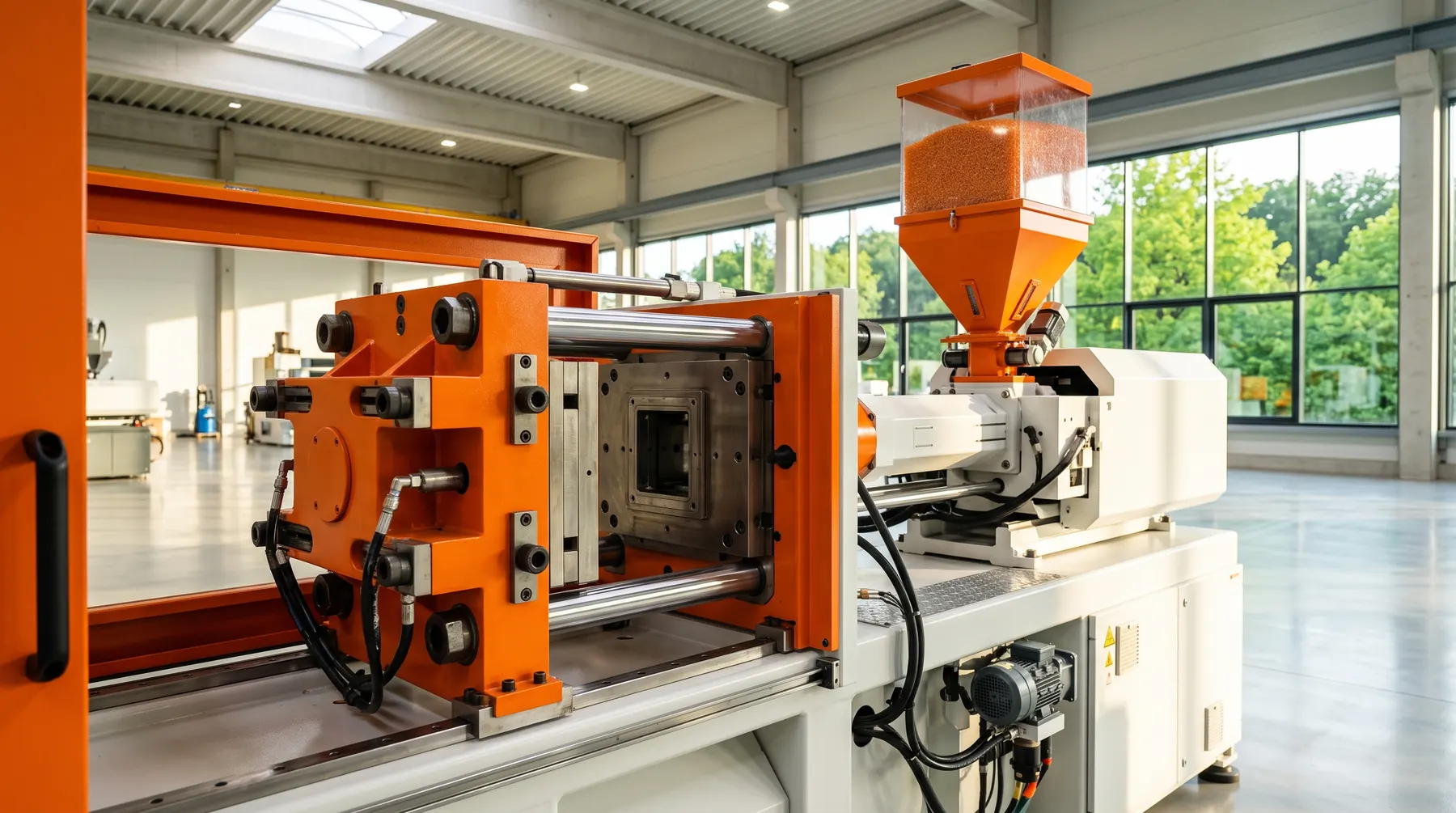
Core machine subsystems: Injection unit and clamping mechanism
An industrial injection molding machine consists of two main operational assemblies mounted on a rigid bed frame: the injection unit and the clamping unit.
The injection unit houses the material hopper, the heated cylindrical barrel, and the reciprocating screw. Pellets feed gravity-assisted into the screw flights. As the screw turns, internal friction generates sixty to eighty percent of the required thermal energy, with electric heater bands providing precise temperature zoning from feed throat to nozzle tip.
The clamping unit holds the mold halves in precise alignment under high pressure. Machine capacity is universally classified by clamping tonnage, representing the maximum force the clamp exerts to resist opening forces during injection. Clamping requirements depend directly on part projected area multiplied by average cavity pressure.
Anatomy of an injection mold: Cores, cavities, runners, and gates
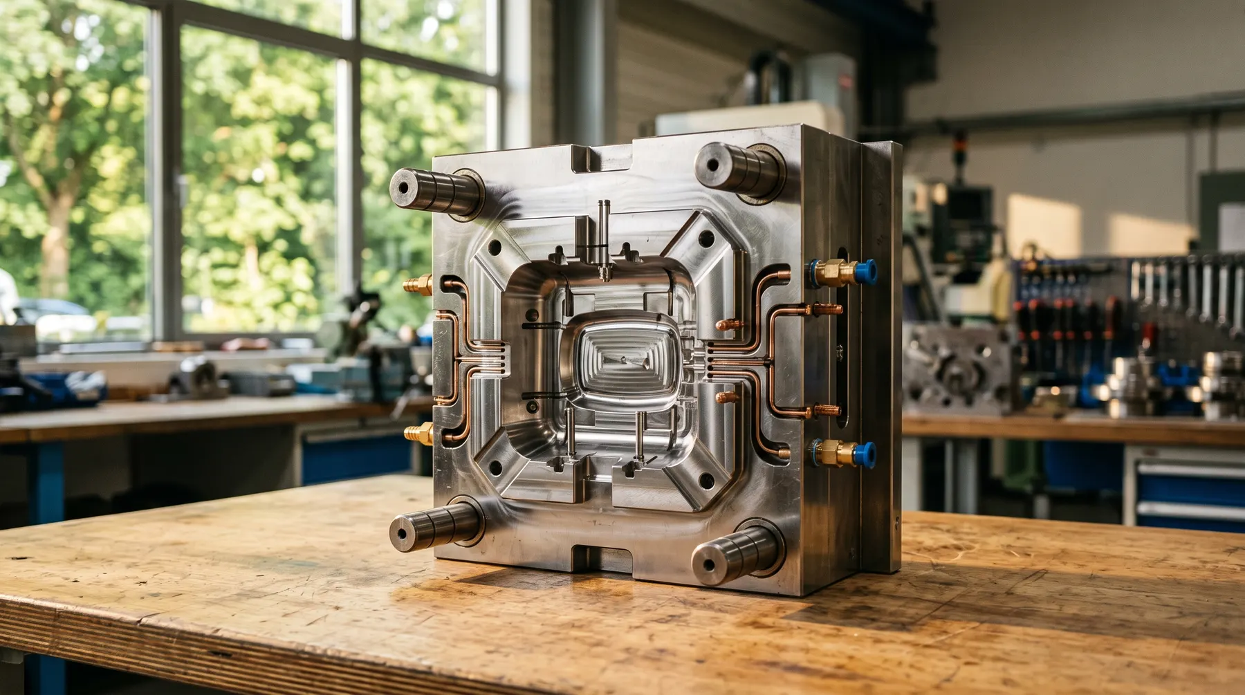
The mold tooling represents the precision heart of the process. The mold consists of two primary sides: the stationary side (A-plate or cavity side) facing the injection nozzle, and the movable side (B-plate or core side) mounted to the moving machine platen.
The cavity creates external cosmetic surfaces, while the core forms internal functional features, ribs, and bosses. Fluid passes from the machine nozzle through a central sprue, distributes through runners, and enters each cavity through engineered gates.
In cold runner molds, runner channels solidify with each shot and are ejected alongside the part, requiring separation and recycling. In hot runner systems, electrically heated manifolds keep the plastic molten within the mold channels, eliminating runner waste and shortening overall cycle time.

Process parameters and scientific molding principles
Modern injection molding relies on scientific molding methodology: establishing repeatable cavity pressure, fill rate, and cooling dynamics independent of individual machine quirks.
The four primary processing variables are temperature (melt and mold temperature), pressure (injection, pack, and back pressure), velocity (injection fill speed profile), and cooling time. Controlling mold temperature through continuous water thermoregulation circuits prevents internal residual stresses and guarantees consistent dimensional tolerances across long batch runs.
Recommended technical pages
Related manufacturing processes and guides
Explore engineering documentation, process limits, and material guidelines.
Design guidelines & tolerances
DFM rules for wall thickness, draft angles, ribs, and ISO 20457 tolerance classes.

Materials guide
Comparison of ABS, PC, PA, PP, POM, and TPE resins with EU regulatory notes.
Tooling & mold making
In-house mold design, CNC machining, EDM, T1 sampling, and mold life.
Frequently asked questions
Direct technical answers on processes, tooling, standards and commercial terms.
What are the fundamental steps of the injection molding cycle?
The cycle consists of six sequential steps: clamp closing, melt injection, pack and hold pressure, part cooling alongside screw plasticizing, mold opening, and mechanical part ejection.
What is clamp force and how is it determined?
Clamp force is the compressive tonnage exerted by the machine to keep mold halves sealed during injection. It is calculated by multiplying the total projected surface area of parts and runners by cavity pressure, plus a safety margin.
What causes sink marks and how can designers prevent them?
Sink marks occur when thick plastic sections cool and shrink away from mold walls. Designers prevent sink marks by maintaining uniform wall thickness, coring out thick masses, and designing ribs at fifty to sixty percent of nominal wall thickness.
What is flash and what shop floor conditions cause it?
Flash is thin excess polymer forced beyond parting line boundaries. It is caused by excessive injection pressure, thermal expansion of over-packed cavities, worn mold shut-off surfaces, or insufficient machine clamp tonnage.
What is the operational difference between hot runner and cold runner tooling?
Cold runners solidify during every cycle and are ejected with the parts as scrap or regrind. Hot runners maintain molten resin inside heated internal manifolds, eliminating runner scrap and reducing overall cycle time at higher initial tooling cost.
Optimize your part for the molding cycle
Send STEP CAD models for a thorough cycle and defect analysis. We assess cooling channels, wall consistency, and tooling specifications.